English
 Pусский
 Español
 Português
Walk-Behind Vibratory Roller
The walk-behind vibratory road roller generally takes two forms: single-drum and tandem models. Both types are compatible with asphalt repair and granular soil compaction jobs.
This walk-behind unit differs from most of chain- or belt-driven road rollers in that it is completely powered by the hydraulic system. Such a system is an assembly of hydraulic pumps and motors that supply power for vibrating and traveling. It does not require any alterations to the system structure so as to obtain varied vibrating and riding speeds that meet different job site requirements.
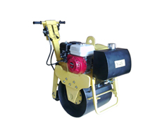
Single-Drum Unit
RL-450 RL-600 RL-800
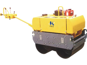
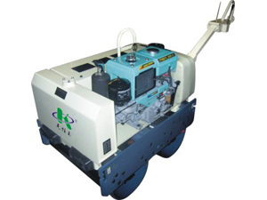
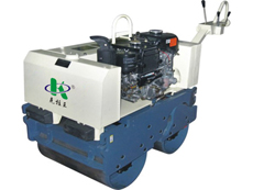
Tandem or Double-Drum Unit
RL-500D RL-600D RL-700D
VR-500 VR-600 VR-650
Applications
The RL series vibratory road roller uses one powerful output shaft to drive both drums to vibrate and compact the ground.
Compaction would be more effective if this road roller is used on most of the job sites other than the soft ground that contains too much moisture. Typical uses of the roller are in the soil, sand, gravel, and asphalt compaction sites.
The hydraulic vibrating system operates independently of the hydraulic drive system. Both hydraulic systems use hydro-static pressure to generate power for vibrating and traveling. The features of hydro-static pressure allow the roller to provide smooth operation even on a slope. This makes inclined terrain application a possibility.
The roller would not be used for large projects where the ground is already compacted, since hard soil causes damage to the roller. Be sure to avoid the said applications.
Structure
The top part the roller is comprised of engine, hydraulic pump, oil tank, electromagnetic clutch, water tank, and operating lever. It is fixed to the frame to connect with the bottom part through the shock-absorbing rubber.
The lower part has a vibrator, drum, and frame. The vibrator unit generates vibration in between both drums. Each of drums is traveled by separate hydraulic motor. The frame constitutes the main body.
Power Transfer
1. A water-cooled single-cylinder diesel engine or an alternative air-cooled unit is fitted into the roller. Output power of the motor is transferred via the centrifugal clutch. The purpose of the clutch is to engage when the engine speeds up and disengage when the engine is idling.
2. The drum features a built-in clutch that transfers power from the engine to the drum and provides energy for drum riding forward.
3. The hydraulic pump generates hydraulic pressure through out hydraulic hose coming from oil tank. The pressure is converted into torque to drive the drum shaft for rotation thereby going forward.
4. The traveling speed of forward or reverse motion is adjusted by the movement of operating lever.
5. The vibration action is generated the vibrator unit, exerting vibrating force into the ground for compaction.
Related Names
Concrete Road Paver | Engineering Equipment | Concrete Compaction Machine